MFD MINI AAT Automatic Tracking Antenna Tracking PTZ
Original price was: $68.00.$34.00Current price is: $34.00.
Description
1. Product Introduction
The MyflyDream Mini Crossbow Auto-Tracking Gimbal (CrossbowMini AAT) is designed for UAV antenna systems. Its design goal is to provide the UAV system with omnidirectional, high-gain signal reception. To achieve better signal reception quality, a high-gain receiving antenna is desirable. However, high-gain antennas often have a narrow effective angle. The MFD Crossbow AAT is designed to address the difficulty of maintaining an optimal transmit and receive angle with directional antennas during UAV flight.
The CrossbowMini AAT requires the latitude, longitude, and altitude of the tracked target (drone). To achieve this, we offer several solutions, including:
- Transmitting tracked target information via a wireless analog video link. The drone requires installing our TeleFlyPro tracking module or using our MFDAP/MFD Crosshair AP flight controller.
- Some high-definition transmitters have built-in serial communication. A TeleFlyPro module can be installed on the aircraft to transmit tracking data to the Crossbow AAT via the serial port.
- Transmitting drone information via a digital radio using the MAVLink protocol. If the user’s system already includes a data radio and a flight controller that supports the MAVUnk protocol, we simply share the data radio’s TX line with the Crossbow AAT to achieve tracking.
- Custom interpretation of other proprietary protocols is supported. Please contact us for specific requirements.
CrossbowMiniAAT Main Specifications:
2. Installation and Wiring
1. The bottom of the gimbal has a standard 1A-20 tripod thread interface. Please purchase a sturdy and reliable tripod and mount the AAT on the quick-release plate, ensuring that the anti-rotation protrusion on the tripod quick-release plate is inserted into the corresponding anti-rotation hole on the bottom of the AAT. The AAT requires a 12V~16V (3S~4S) DC power supply. There is an XT30 socket on the AAT panel; please connect a compatible power source.
2. Please securely mount your antenna to the AAT’s antenna mounting bracket. Avoid using antennas with ferromagnetic materials, as this may affect the functioning of the AAT’s built-in compass. If possible, use non-magnetic materials such as stainless steel wire and aluminum. Connect the analog video receiver to the 3-pin socket on the back of the gimbal’s tilt servo. The wiring diagram for this socket is as follows:
3. Preliminary Test
After verifying the wiring and ensuring the tripod is secure, power on the gimbal for testing. Under normal circumstances, the gimbal’s tilt angle will return to 0 degrees (pointing toward the horizon) and the antenna will point straight ahead. The panel screen will display the following information:
- Bat#/GPS: alternately displays the gimbal’s current power supply voltage and the number of onboard GPS satellites.
- Dst: Current distance from home. N/A indicates not available.
- Alt: Current aircraft altitude relative to home. N/A indicates not available.
- Azim: Current aircraft azimuth relative to home. N/A indicates not available.
- VLink/DLink: Current downlink signal quality (80%). Depending on whether the video or digital link is being used, the display will show Wuink or DLinkDr, indicating the azimuth angle of the gimbal base.
When both the aircraft and gimbal are powered on, the gimbal’s video output port should display the onboard camera image. The on-screen WLink will indicate the signal link quality. If the Vink display shows a signal strength of 0, check that the flight control is set to VB1 encoding, V2 version technology.
4. Field Usage Steps:
- Power on both the aircraft and the radio. Confirm that the signal quality displayed on the radio’s VLink is not 0.2. Once the number of satellites is sufficient, for example, 8 or more, the flight control will perform the Set Home operation. If communication is normal, the gimbal’s small screen will display “Set Home” and initialize the home position.
- You can also briefly press the right button to set the gimbal’s home position.
- Once the aircraft is 10 meters away, the radio will begin automatic tracking.
Gimbal Menu Operation Guide
Main Screen Button Operations:
- Left Button: Long press to enter the menu.
- Right Button: Short press to select the corresponding column.
Menu Screen:
- Yaw Trimm: Corrects the gimbal tracking deviation in degrees. Adjust the value from -15 to +15 using the right button.
- CalCompass: Rotate the entire AAT horizontally at least one full rotation to calibrate the internal magnetic compass.
- CompassMMod: Compass Usage (Options: OnlyPoweron, Always, Never).
- AIways: Always use the magnetic compass.
- Exit: Exit the menu.
For further details on the calibration and operation of the gimbal, please refer to the user manual or contact our support team.
Related products
-
Sale!

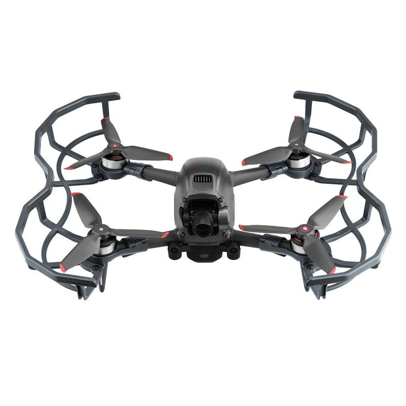
DJI FPV Propeller Guard Lens Cover Cap Antenna Signal Extender Landing Gear Propeller Box for DJI FPV Comb Drone Accessories Type A
Original price was: $27.55.$16.53Current price is: $16.53. Add to cart -
Sale!
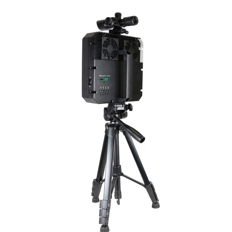
70W Handheld Anti Drone Device – 10 Band 1.5KM High Power Portable Drone UAV Signal With Sight Rail and 1/4 inch Tripod Mounting Hole, Build In Directional Antennas
Original price was: $6,500.00.$148.00Current price is: $148.00. Add to cart -
Sale!
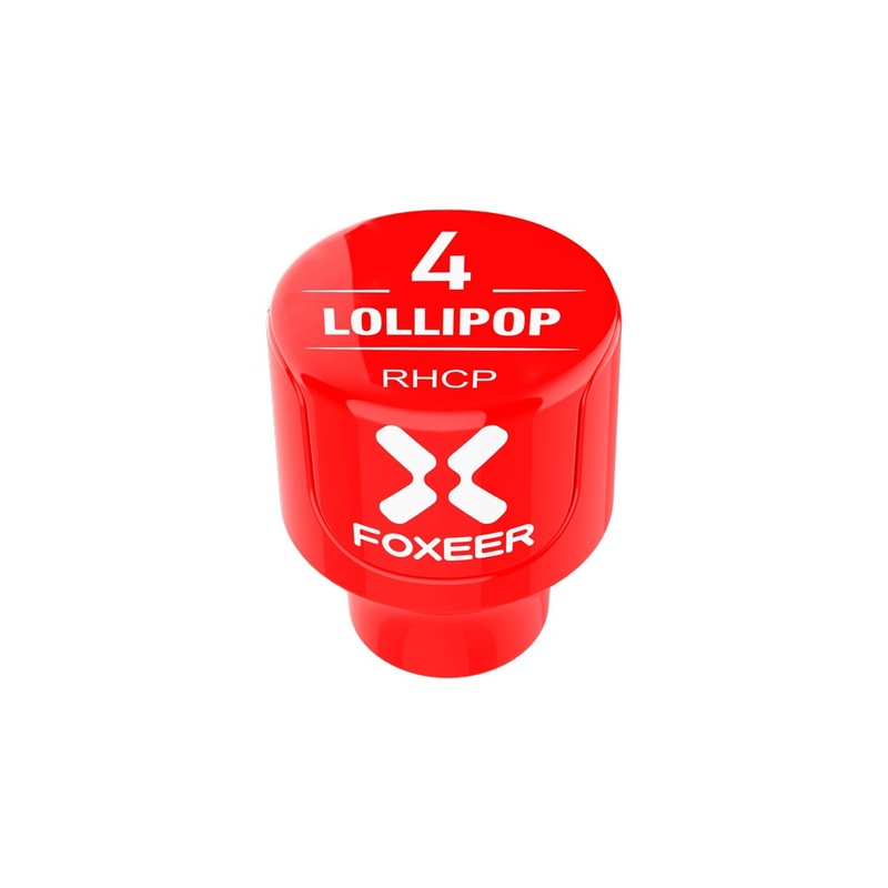
Foxeer Lollipop 4 FPV Antenna Set (2pcs) 2.6dBi 5.8G Omni Stubby, SMA/RPSMA, RHCP/LHCP white
Original price was: $27.86.$16.72Current price is: $16.72. Add to cart -
Sale!
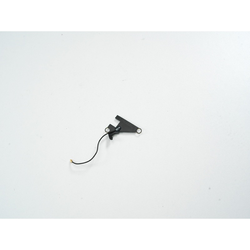
DJI FPV Drone ADS-B Antenna (Left)
Original price was: $13.00.$7.80Current price is: $7.80. Add to cart
Reviews
There are no reviews yet.