DFRobot SEN0142 MPU6050 6 DOF Gyroscope Accelerometer IMU Module with I2C Digital Motion Processor for Arduino & Robotics
Original price was: $25.00.$15.00Current price is: $15.00.
Description
Overview
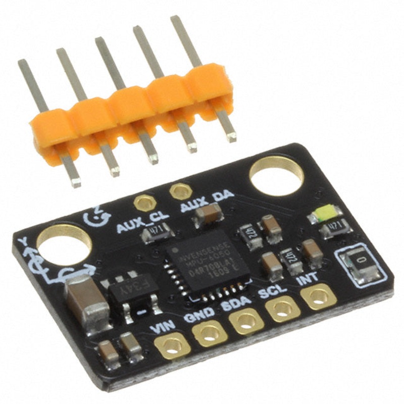
The DFRobot SEN0142 MPU6050 6 DOF IMU module integrates a 3-axis gyroscope and 3-axis accelerometer on a single chip, delivering accurate motion sensing for robotics, drones, wearable devices, and Arduino projects. Featuring a Digital Motion Processor (DMP), it supports advanced 6-axis and 9-axis MotionFusion algorithms, enabling quaternion, Euler angle, and raw sensor data output. With a wide input voltage range of 3V5V, the MPU6050 can be directly connected to Arduino and other microcontrollers for real-time motion tracking and gesture detection.
Key Features
-
Combines 3-axis gyroscope and 3-axis accelerometer in one chip
-
Programmable accelerometer range: 2g, 4g, 8g, 16g
-
Gyroscope sensitivity: 250, 500, 1000, 2000 dps
-
Digital Motion Processor (DMP) for onboard MotionFusion and gesture recognition
-
I2C digital interface supports matrix, quaternion, Euler, and raw data formats
-
Embedded bias & compass calibration for improved accuracy
-
Compatible with Arduino and wearable electronics via I2Cdevlib
Specifications
-
Working Voltage: 35 V
-
Output: I2C digital (6/9-axis MotionFusion data)
-
Accelerometer: 2g / 4g / 8g / 16g programmable range
-
Gyroscope: 250 / 500 / 1000 / 2000 dps sensitivity
-
Data Format: Rotation matrix, quaternion, Euler angle, raw data
-
Dimensions: 14 21 mm
Applications
-
Robotics motion sensing
-
Arduino & DIY electronics projects
-
Human-Computer Interaction (HCI)
-
Wearable devices and gesture control
-
Navigation and balancing systems (e.g., Segway-type transporters)
-
Drone stabilization and motion tracking
Details
Sample Code
Please download thelibrariesfor the all the IMU sensors first!
// I2C device class (I2Cdev) demonstration Arduino sketch for MPU6050 class// 10/7/2011 by Jeff Rowberg // Updates should (hopefully) always be available at https://github.com/jrowberg/i2cdevlib//// Changelog:// 2013-05-08 – added multiple output formats// – added seamless Fastwire support// 2011-10-07 – initial release/* ============================================I2Cdev device library code is placed under the MIT licenseCopyright (c) 2011 Jeff RowbergPermission is hereby granted, free of charge, to any person obtaining a copyof this software and associated documentation files (the “Software”), to dealin the Software without restriction, including without limitation the rightsto use, copy, modify, merge, publish, distribute, sublicense, and/or sellcopies of the Software, and to permit persons to whom the Software isfurnished to do so, subject to the following conditions:The above copyright notice and this permission notice shall be included inall copies or substantial portions of the Software.THE SOFTWARE IS PROVIDED “AS IS”, WITHOUT WARRANTY OF ANY KIND, EXPRESS ORIMPLIED, INCLUDING BUT NOT LIMITED TO THE WARRANTIES OF MERCHANTABILITY,FITNESS FOR A PARTICULAR PURPOSE AND NONINFRINGEMENT. IN NO EVENT SHALL THEAUTHORS OR COPYRIGHT HOLDERS BE LIABLE FOR ANY CLAIM, DAMAGES OR OTHERLIABILITY, WHETHER IN AN ACTION OF CONTRACT, TORT OR OTHERWISE, ARISING FROM,OUT OF OR IN CONNECTION WITH THE SOFTWARE OR THE USE OR OTHER DEALINGS INTHE SOFTWARE.===============================================*/// I2Cdev and MPU6050 must be installed as libraries, or else the .cpp/.h files// for both classes must be in the include path of your project#include “I2Cdev.h”#include “MPU6050.h”// Arduino Wire library is required if I2Cdev I2CDEV_ARDUINO_WIRE implementation// is used in I2Cdev.h#if I2CDEV_IMPLEMENTATION == I2CDEV_ARDUINO_WIRE #include “Wire.h”#endif// class default I2C address is 0x68// specific I2C addresses may be passed as a parameter here// AD0 low = 0x68 (default for InvenSense evaluation board)// AD0 high = 0x69MPU6050 accelgyro;//MPU6050 accelgyro(0x69); // <-- use for AD0 high//MPU6050 accelgyro(0x68, &Wire1); // <-- use for AD0 low, but 2nd Wire (TWI/I2C) objectint16_t ax, ay, az;int16_t gx, gy, gz;// uncomment “OUTPUT_READABLE_ACCELGYRO” if you want to see a tab-separated// list of the accel X/Y/Z and then gyro X/Y/Z values in decimal. Easy to read,// not so easy to parse, and slow(er) over UART.#define OUTPUT_READABLE_ACCELGYRO// uncomment “OUTPUT_BINARY_ACCELGYRO” to send all 6 axes of data as 16-bit// binary, one right after the other. This is very fast (as fast as possible// without compression or data loss), and easy to parse, but impossible to read// for a human.//#define OUTPUT_BINARY_ACCELGYRO#define LED_PIN 13bool blinkState = false;void setup() { // join I2C bus (I2Cdev library doesn’t do this automatically) #if I2CDEV_IMPLEMENTATION == I2CDEV_ARDUINO_WIRE Wire.begin(); #elif I2CDEV_IMPLEMENTATION == I2CDEV_BUILTIN_FASTWIRE Fastwire::setup(400, true); #endif // initialize serial communication // (38400 chosen because it works as well at 8MHz as it does at 16MHz, but // it’s really up to you depending on your project) Serial.begin(38400); // initialize device Serial.println(“Initializing I2C devices…”); accelgyro.initialize(); // verify connection Serial.println(“Testing device connections…”); Serial.println(accelgyro.testConnection() ? “MPU6050 connection successful” : “MPU6050 connection failed”); // use the code below to change accel/gyro offset values /* Serial.println(“Updating internal sensor offsets…”); // -76-23591688000 Serial.print(accelgyro.getXAccelOffset()); Serial.print(“”); // -76 Serial.print(accelgyro.getYAccelOffset()); Serial.print(“”); // -2359 Serial.print(accelgyro.getZAccelOffset()); Serial.print(“”); // 1688 Serial.print(accelgyro.getXGyroOffset()); Serial.print(“”); // 0 Serial.print(accelgyro.getYGyroOffset()); Serial.print(“”); // 0 Serial.print(accelgyro.getZGyroOffset()); Serial.print(“”); // 0 Serial.print(“”); accelgyro.setXGyroOffset(220); accelgyro.setYGyroOffset(76); accelgyro.setZGyroOffset(-85); Serial.print(accelgyro.getXAccelOffset()); Serial.print(“”); // -76 Serial.print(accelgyro.getYAccelOffset()); Serial.print(“”); // -2359 Serial.print(accelgyro.getZAccelOffset()); Serial.print(“”); // 1688 Serial.print(accelgyro.getXGyroOffset()); Serial.print(“”); // 0 Serial.print(accelgyro.getYGyroOffset()); Serial.print(“”); // 0 Serial.print(accelgyro.getZGyroOffset()); Serial.print(“”); // 0 Serial.print(“”); */ // configure Arduino LED pin for output pinMode(LED_PIN, OUTPUT);}void loop() { // read raw accel/gyro measurements from device accelgyro.getMotion6(&ax, &ay, &az, &gx, &gy, &gz); // these methods (and a few others) are also available //accelgyro.getAcceleration(&ax, &ay, &az); //accelgyro.getRotation(&gx, &gy, &gz); #ifdef OUTPUT_READABLE_ACCELGYRO // display tab-separated accel/gyro x/y/z values Serial.print(“a/g:”); Serial.print(ax); Serial.print(“”); Serial.print(ay); Serial.print(“”); Serial.print(az); Serial.print(“”); Serial.print(gx); Serial.print(“”); Serial.print(gy); Serial.print(“”); Serial.println(gz); #endif #ifdef OUTPUT_BINARY_ACCELGYRO Serial.write((uint8_t)(ax >> 8)); Serial.write((uint8_t)(ax & 0xFF)); Serial.write((uint8_t)(ay >> 8)); Serial.write((uint8_t)(ay & 0xFF)); Serial.write((uint8_t)(az >> 8)); Serial.write((uint8_t)(az & 0xFF)); Serial.write((uint8_t)(gx >> 8)); Serial.write((uint8_t)(gx & 0xFF)); Serial.write((uint8_t)(gy >> 8)); Serial.write((uint8_t)(gy & 0xFF)); Serial.write((uint8_t)(gz >> 8)); Serial.write((uint8_t)(gz & 0xFF)); #endif // blink LED to indicate activity blinkState = !blinkState; digitalWrite(LED_PIN, blinkState); delay(100);}
Related products
-
Sale!

MatekSys ASPD-AUAV Digital AirSpeed Sensor for ArduPilot RC Aircraft, DroneCAN CAN/I2C/UART (MSP)
Original price was: $149.00.$74.50Current price is: $74.50. Add to cart -
Sale!
JRT TC22 905nm Eye-Safe Laser Rangefinder Measuring Module, 3-700m, UART TTL, 43x22mm, Sight/Night Vision
Original price was: $287.16.$143.58Current price is: $143.58. Add to cart -
Sale!
WitMotion WT901SDCL 9-Axis Offline Accelerometer Data Logger (MPU9250, 0.1200 Hz, 16 GB SD, RTC)
Original price was: $69.00.$34.50Current price is: $34.50. Add to cart -
Sale!
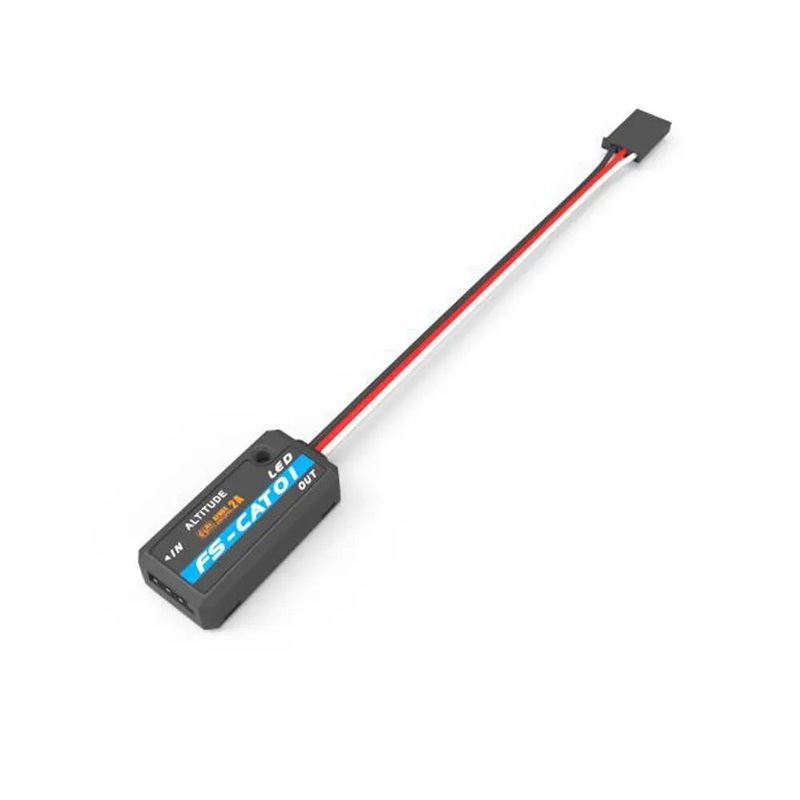
FLYSKY FS-CAT01 Altitude Sensor – IBUS Data Port for FLYSKY I6X I6S NV14 PL18 Transmitter IA6B IA10B Receiver DIY Parts 1PC
Original price was: $12.39.$7.43Current price is: $7.43. Add to cart
Reviews
There are no reviews yet.